Dealing with part shortage - Microchip edition

Illustration

For a small electronics project of mine, I needed literally only one output pin. My go-to part for these situations is PIC10F200. It’s a 6-pin SOT-23 device offering internal oscillator and not much more. Microcontrollers don’t really get smaller/simpler than this.

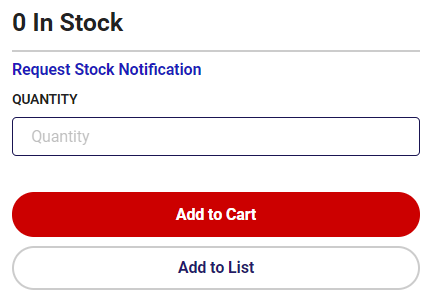
Due to the hamster habits I have, I actually had enough enough parts to finish up the prototype so the only thing left was to order a few more parts of DigiKey. Well, as many components lately, my favorite PIC was out of stock.

However, when one door closes, another one opens. Microchip is really good at keeping pinout similar over multiple microcontrollers. And DigiKey had PIC10F202, PIC10F206, PIC10F220, PIC10F222, and PIC10LF322 available in stock. While all these PICs are slightly different, they share the same basic pinout. And for my project any of them would do. Even if I used some less common feature, Microchip often has multiple products differing only in memory amount.

While hardware might be similar enough, firmware does have significant differences - especially between older PIC10F206 and newer PIC10LF322 setup. Even turning LED on/off uses different registers between them. Instead of having different firmware for each, one can make use of compiler directives and check which PIC is actually being used. Something like this:

#if defined(_10F200) || defined(_10F202) || defined(_10F204) || defined(_10F206)
    GP2 = 0;                // turn off GP2
    TRISGPIO = 0b11111011;  // GP2 is output
#else
    LATAbits.LATA2 = 0;    // turn off RA2
    TRISAbits.TRISA2 = 0;  // RA2 is output
#endif

While out-of-stock syndrome has hit Microchip too, with a bit of care, they do make transition feasible if not always trivial.

Adding USB to A-BFastiron SS-305MP

Illustration

I needed a cheap power supply for a project and it was easy to find a nice one in A-BFastiron SS-305MP. It was small enough, looked good, and had shiny display. What could man want more?

Well, when I got it and saw cutout for USB, I know what more I wanted. An USB port.

And strangely enough once you open the power supply, you’ll find connector providing about 8.2 V already there without anything to plug into. It’s almost as if somebody placed it there to be an input for 5V linear voltage converter and then later figured electronics and heatsinking would cost too much and covered the hole. And yes, it’s a proper hole cover that you can remove - no drilling necessary.

If you open power supply you will even find standoffs already in place. It’s simply begging to have PCB mounted in.

First thing to figure out was which USB connector will fit. Searching on DigiKey found quite a few of them roughly matching the dimensions. So I just selected the cheapest one that matched standard footprint. And yes, looking on side you might find it protruding a bit too much but not criminally so. It might be original designers were fine with this or the had a custom length connector in mind. For me this was as good as it gets.

With connector found, it was time to figure PCB. And I decided to keep it really simple. The whole setup would revolve around VXO7805-1000. It’s a nice DC-DC switching regulator that will take any input higher than 8 V and drop it down to 5 V with some efficiency. In its pinout it emulates beloved LM7805 but at 90% efficiency and without all the heat.

Regulator itself requires just two capacitors and I decided to go just with them. I was tempted to add a smaller 1 µF capacitor to output and maybe even a 100 nF one for decoupling purposes but decided against it. Due to wide variety of cables and outputs USB device might face, all of them already have more than sufficient decoupling and adding more wouldn’t really do anything. So why waste a component.

The only really unneeded components would be an LED and its accompanying resistor. While they serve no function, I really love to have an indicator of output. If there was ever an issue, looking at LED would at least tell me if power is going out. And quite often that’s quite a big help.

Speaking of power going out, I don’t consider a fuse optional. It’s a minimum you need in this setup. Another thing I would consider bare minimum for power supply would be a short-circuit detection but that’s fortunately already a part of voltage regulator. And yes, I could have gone further, especially by adding reverse polarity protection to the input and I was tempted but in reality you’ll just connect this thing once and leave it connected. As long as you connect it correctly the first time, you’re good.

Illustration

Connecting all this to the power is entrusted to any JST-XH 2-pin cable - 10 cm in length. Just make sure that the negative wire is going next to COM marking on the power supply motherboard. If in doubt, just double-check with voltmeter.

And that’s it. For a few bucks more and some extra soldering, we have a nice 500 mA USB port at the front of the power supply. Just in case we need it.

On GitHub you’ll find source files and releases with gerbers and part list.

Changing A-BFastiron SS-305MP Binding Posts

Illustration

I needed a cheap power supply for a project and it was easy to find a nice one in A-BFastiron SS-305MP. It was small enough, looked good, and had shiny display. What could man want more?

Well, how about proper binding posts?

And no, I am not only talking about quality albeit one coming with it are quite flimsy and it already arrived with one cracked. I am talking about spacing. I simply hate when binding posts don’t observe standard ¾" distance between them.

And this power supply almost had it right. I measured spacing to be a smidgen over 20 mm while standard would call for 19.05 mm. With such a small difference, there was literally no reason to go non-standard. But non-standard they went.

If you open the power supply, you’ll see that binding posts are held by the PCB in the back. Thick wires are soldered onto it and nuts are used to connect to posts themselves. So the whole operation can be done with a simple PCB update with correct spacing. Only thing needed extra is a bit of filing action and you can reassemble it all.

However, since my binding post was already cracked, I decided to swap them for Pomona 3760 (black and red) set. But that brought another issue - panel cutout for them is completely different. And yes, a patient man might shape it enough, but for those with 3D printer there’s an easier solution.

Illustration

To mount it all, I used some nice red MH Build PLA to print really tight mounting base and spacer for posts.

After filing plastic a bit to expand holes toward each other, I placed binding posts into the printed base, pushed it through the hole, used another 3D printed spacer on inside and added some more height to set using spacers that came with binding posts themselves. Then in goes the custom PCB and finally all can be fastened using lock washer and nut that cane with posts.

Result are nice binding posts at proper spacing. :)

On GitHub you’ll find source files and releases with gerbers and part list. 3D model can be found on TinkerCAD.


PS: The only downside of Pomona is that it uses ¼" imperial nuts while the power supply originally had 7 mm nuts. So, in addition to metric socket set you already have, you’ll need a witchcraft-sized set too.

Prepping Image for ESXi

I like using vboxmanage for disk conversions. When dealing with major formats it often can do everything I need. For example, if I wanted to convert raw disk image to .vmdk, it’s easy:

vboxmanage convertdd in.raw --format VMDK out.vmdk

However, sometime this simple tool is too simple. For example, using that image with ESXi, any modern version will just give you “Not a supported disk format (sparse VMDK version too old)”.

But it’s not like vboxmanage is the only game in town. For example one can use qemu-img.

qemu-img convert -f raw -O vmdk in.raw out.vmdk

Different tool, same error.

For ESXi to work, we need to tweak options a bit.

qemu-img convert -f raw -O vmdk \\ -o adapter\_type=lsilogic,subformat=streamOptimized,compat6 \\ in.raw out.vmdk

And this one does the trick.

Well Grounded

Playing with electronics as a hobby has its advantages. Most notably, I don’t need to deal with high-speed signals or EMC most of the time. However, in the days of faster and faster I/O, high-frequency content “sneaks in” whether you want it or not. Just because your microcontroller works at 48 MHz, that doesn’t mean your I/O edge is not (much) faster. And sorting out those issues is hard.

Fortunately, there are many “rule-of-the-thumb” guides out there, but I found none better than Rick Hartley’s. Well worth the watch.